A hollow sphere, and a different way to slice it
Two demonstrations in March used the same hollow sphere to show why a slicing strategy matters alongside the shape of the part.
A simple shape with an awkward question
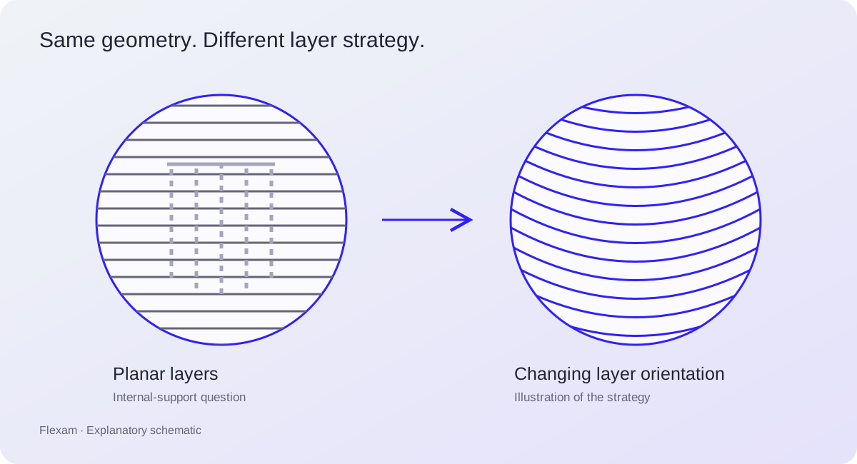
A hollow sphere looks like a simple model, which makes it a useful place to start a technical explanation. In the first demonstration we shared on 19 March, the part is sliced with a conventional layer arrangement. The outside looks clean, but support structures appear in the space inside the sphere. That raises a practical question before the job ever reaches a printer: how would those supports be removed?
The problem is not visible if we only look at the outer surface of the model. We need to look inside and consider how the material would be built. A cavity can turn an ordinary preparation decision into a question about access after printing. In this example, the inside of the part is where the interesting discussion begins.
Keeping the model, changing the strategy
Our follow-up on 27 March kept the sphere and changed the approach to slicing it. The software uses conical surfaces and gradually changes their orientation through the shape. This produces a different arrangement of paths inside the same model. The change is in the planned build strategy, rather than in a redesign of the sphere.
Flat layers give one way to divide a model into sections for printing. Non-planar slicing introduces other surfaces that can be used to organise those sections. Conical surfaces are one example, and this demonstration makes their changing orientation easier to follow. The drawing accompanying this article separates the two approaches so that the difference is visible without reading machine code.
What the comparison tells us
For us, this is a concrete way to explain why multi-axis preparation starts before machine motion. We have to think about the direction in which a part will be built, as well as its geometry. That direction changes the paths we ask the machine to follow. It can also change where support questions arise in the planned process.
The two March demonstrations show a strategy comparison, rather than a result that applies to every hollow part. A physical job still needs a suitable machine, material and process setup. That connection between geometry, strategy and the actual print is what we work on at Flexam. The sphere gives us a clear example to discuss, with the question about its inside doing much of the explaining.